

Traffic congestion in major cities is a bane for commuters, but as a daily affair, we have all gotten used to it. Imagine, how would you feel if your house was on fire and you waited for the fire truck to arrive, only to be informed that it was stuck in traffic? The intelligent transportation system is the need of the day. With global impetus on smart cities, this need will soon turn into reality.
This post was originally published in Twilio Blog
When congestion meets an emergency situation, it can lead to loss of lives and property. That is where an Intelligent Transportation System (ITS) kicks in. A citywide ITS based infrastructure keeps tab of city traffic and controls the traffic control signals to manage traffic pile up. In this post, we will witness how an ITS can be automated to facilitate seamless movement of emergency vehicles, like ambulances and fire trucks.
Intelligent Transportation Systems: Bridging the Gap with IoT
Internet of Things has been around for a few years now, and its novelty has already given way to practicality across various industries. Technologies such as GSM and more recently LPWAN have enabled us to connect device which are either on the move or accessible only remotely. And with GPS, it is quite easy to track vehicles as well. For managing emergency vehicles on the move, we can employ a set of these technologies to make a smart and intelligent transportation system.
That leads to our use case today. We want to build an ITS that can sense an approaching emergency vehicle at a traffic signal, and then direct the traffic signal to turn green. Once the vehicle crosses the intersection, the ITS redirects the traffic signal to roll back to its normal operation.
We are going to build a model ITS system which is capable of sensing emergency vehicles and controlling the approaching traffic lights. As this system will comprise both hardware and software components, let’s dive in to get a closer look at each of system components.
Hardware Components of The System
In a real-world application, the best way to track the location and direction of a moving vehicle is through a GPS device. We also have another device that can be attached to the traffic signal equipment to control the operation on the traffic lights. Both these devices need to be connected to the Internet.
However, to simplify the setup for our model ITS, the Raspberry Pi 3 can be used as traffic signal equipment.
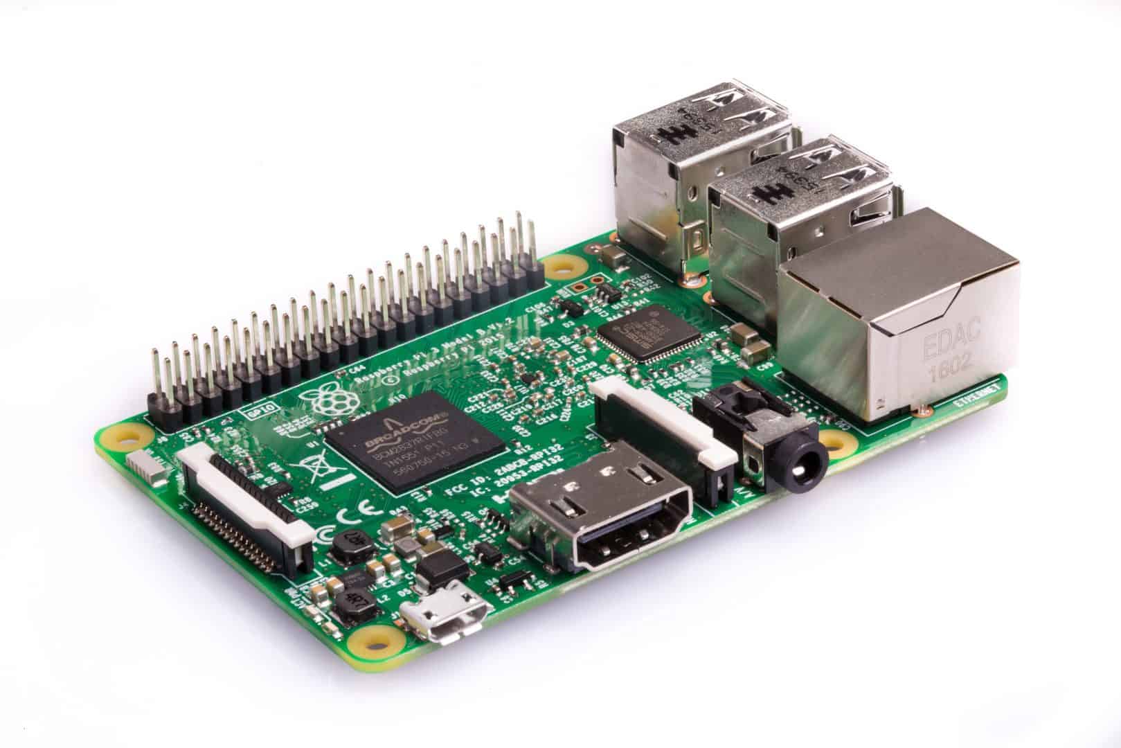
[thrive_text_block color=”teal” headline=”Looking for Raspberry Pi Programming Help?”]If you are looking for help in programming Raspberry Pi hardware interfaces, then check our Raspberry Pi Resource Page [/thrive_text_block]
Software for a Demo ITS
The GPS device component of the emergency vehicle is simulated in software for today’s demo. It will replicate the movement of the vehicle along a predefined route. It sends the GPS location along that route and gives an impression of the vehicle in motion by sending GPS data periodically.
Assuming that we have the traffic signals and emergency vehicles hooked up to the internet, how do we connect them in such a way that the traffic signal is aware of the approaching emergency vehicles location?
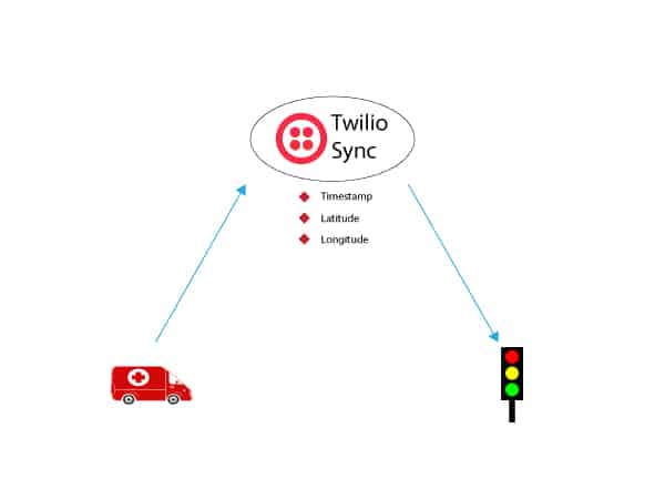
That’s where Twilio Sync comes in and plays the role of an orchestrator.
Twilio Sync is a cloud-based service that makes it super easy to share information between multiple devices connected to the internet. It is a serverless way of sharing your application state between multiple connected components. Think of it as a memoryless way of storing and syncing variables and state information between two application components connected to the internet, akin to the serverless way of deploying applications on the cloud.
To use Sync, first register for a Twilio account and then request an invite to Twilio Sync early access.
Using Sync for an ITS Backend
For our model ITS, we are going to use Twilio Sync to build our ITS backend. Both the emergency vehicle and the traffic signal will be synced up via some form of connectivity, as you can see in the diagram below.
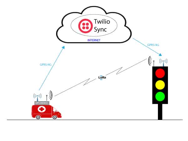
To provide some amount of resilience to the system (considering the fact that it is used for managing emergency vehicles!) we will also use LoRa radio-based point to point connectivity.
Building the Working Setup for ITS
Let’s look at how we can assemble the hardware and software pieces of this system together to build a functional setup.
Before we proceed, here is a quick recap on our model setup. We are going to use the Raspberry Pi3 as the traffic signal and a laptop/computer for simulating the GPS device of the emergency vehicle.
Hardware
As we are using Raspberry Pi 3 to represent the traffic signal hardware, we have connected three LEDs to emulate the red, amber and green signal color of a typical traffic signal. These are interfaced via GPIO with the Raspberry Pi 3. Since we are including communications redundancy, we have also added the LoRa interface as a USB serial device.
Here is the final schematic representation of the Raspberry Pi 3 with the LEDs.

The LoRa module used here is the Microchip RN 2483 and its pinout and the schematic is as follows.
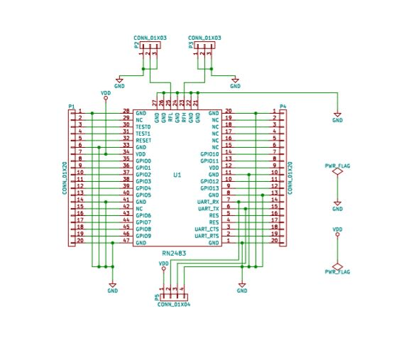
We will use this specific design. You can also purchase the LoRa evaluation kit from Microchip site but their external pinout will be different.
Note: LoRa operates in the ISM radio band which varies from country to country. The RN 2483 module used in this demo is meant for Europe and Asia. If you are in North America then you must check out RN 2903. All the Microchip’s LoRa products are listed here.
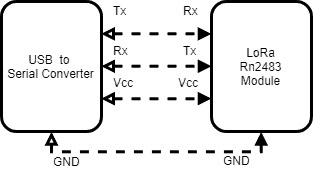
We need to connect the LoRa breakout module to a serial to USB converter so that it can be attached to the USB port of the Raspberry Pi as well as the laptop.
Onboard Software
The entire source code of the software components, written in Python, is available through this GitHub repository.
There are three independent pieces of software that are required to make this system work.
Traffic Signal Software
The traffic signal software runs on the traffic signal for toggling the LEDs and also for setting up the passage for the emergency vehicle.
During initialization, the traffic signal software checks and brings up the LoRa and MQTT interface via the systemInit function.
Checkout the code in Github Gist
The traffic signal listens for the MQTT topic sync/docs/gpsData and subscribes to a callback function, handleEmergencyMessage. This function handles the complete behavior of the signal light toggling based on the GPS location received from the vehicle.
Checkout the code in Github Gist
handleEmergencyMessage calculates the distance between the traffic signal and the vehicle and updates the state. The state can be either NORMAL(0) or CRITICAL(1), meaning that the emergency vehicle is in close proximity to the signal intersection.
Based on the current state, the function updateTrafficSignal gets invoked periodically and takes the appropriate action. For the NORMAL case, it just toggles through the normal sequence of red, amber and green lights. For the CRITICAL state, it holds on to the green light to allow the passage of the emergency vehicle.
Checkout the code in Github Gist
The traffic signal software also runs a thread for LoRa reception. If the GPS device sends a special code to indicate that the primary internet communication failed, loraReceive kicks in and sets the CRITICAL state.
Checkout the code in Github Gist
GPS Device
The GPS device software simulates the behaviour of an emergency vehicle movement for reporting periodic GPS locations. This locations are pre configured along a path defined by the location_list variable in the code.
Checkout the code in Github Gist
Like the traffic signal, the GPS device also needs to initialize the LoRa interface and the Twilio client. This is done via the sys_init function.
Checkout the code in Github Gist
Once initialized, the GPS device publishes the preset GPS locations at a periodic interval. Here is how the data is sent to Twilio Sync. Note that we are using the same MQTT topic endpoint gpsData.
Checkout the code in Github Gist
In case of an exception such as internet connection interruption, the LoRa interface is activated to send a special code to the traffic signal directly.
Note: Currently if the internet connection is interrupted, the Twilio client may not raise the exception immediately and the sending of the LoRa signal might be delayed.
Twilio Sync
This is the hosted, server-side component of Twilio that orchestrates the messages from GPS device to the traffic signal. Both the traffic signal software and GPS device need to be subscribed to this service.
You can follow the accompanying README file to set up the Twilio sync account, as well as set up the hardware and software components of the system.
Let’s Do A Test Run
Now is the moment of truth – let’s test our ITS
Before proceeding, make sure that you have hooked up the traffic signal hardware and GPS device with Twilio Sync via the Internet and have also attached the LoRa module.
Fire up the Raspberry Pi and you should see a standard toggling pattern of the traffic lights as we witness every day.
Next, fire up the GPS device script from the laptop. You also have to make sure that the laptop is in close proximity to the traffic signal hardware so as to enable direct point to point LoRa communication in case it is needed.
The GPS device simulates the movement on the emergency vehicle as per the path trail shown below.
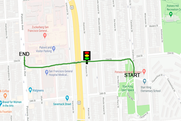
As you can see, the path has an intersection and we assume that the traffic signal hardware is installed there.
The GPS device’s Python script kickstarts the mission for the emergency vehicle. Once the GPS device starts publishing its latest GPS location, Twilio Sync kicks in and makes sure that the location information is updated and shared with the traffic signal.
Check out the demo video to experience how the traffic signal can be controlled based on the position of the emergency vehicle using Twilio Sync. Watch out for the traffic light LEDs and witness how their pattern changes when the emergency vehicle approaches the traffic intersection.
Here is a brief description of the key events that happen in this video:
0:03 – At the beginning, we start the traffic signal software. Following that, you can see the traffic lights toggling in the typical cyclic pattern.
0:17 – We start the movement of the emergency vehicle by starting the GPS device simulation script. Now you can witness the movement of the vehicle and the current GPS location ( latitude and longitude) is logged in the screen.
0:57 – At this point, the emergency vehicle reports its position which triggers a change in the traffic signal toggling pattern. You can see the log message in the traffic signal software that says “Switching to GREEN and Hold”. This means that the traffic signal has detected the emergency vehicle to be in close proximity and has overridden the previous toggling pattern to allow the passage of the emergency vehicle.
1:35 – At this point, the emergency vehicle is assumed to have crossed the intersection and have moved past the minimum distance for proximity from the traffic signal. The signal rolls back the normal cycle of toggling the lights.
1:55 – The emergency vehicle has reached its destination. The traffic signal continues to operate in the normal mode now.
Further Testing
The ideal scenario for this system is to work via always-on internet connectivity. However, in the event of connectivity failure, we have backup LoRa point to point connectivity. It enables the emergency vehicle to send a direct request to the traffic signal to turn green.
However, know that the LoRa device is only activated when the emergency vehicle is in close proximity to the traffic signal. You can test the activation of the traffic signal using LoRa by deliberately disconnecting the internet connection at the GPS device.
Conclusion: ITS with a Raspberry Pi, LoRa, and Twilio Sync
That is it. You have a near functional model of a smart traffic signal which is aware of its surroundings and can be triggered by GPS coordinates and Twilio Sync or LoRa. Such systems can really prove the effectiveness of smart city applications for a growing urban populace.
Don’t forget to check out the full source code of this demonstration and Twilio documentation. Twilio Sync will be generally available soon and we are excited to see what cool stuff you can build with it.
[divider style=’right’]
[content_container max_width=’500′ align=’right’]You can also check out similar proof of concepts that we have built around smart toll system and smart traffic management system using IBM Cloud[/content_container]
