

Wondering how to use the SPI (Serial Peripheral Interface) in Raspberry Pi? This blog post will show you exactly how you can use it to control two external peripheral devices.
What is Serial Peripheral Interface?
Serial Peripheral Interface (SPI) is an synchronous serial bus commonly used to send data between micro controllers and small peripherals such as shift registers, sensors, and SD cards.
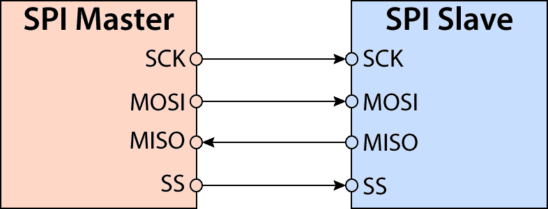
It uses separate clock (SCK) and data lines (MISO, MOSI), along with a select line(SS) to choose among the multiple slave devices.
Controlling Multiple Peripheral Slaves
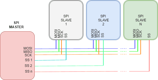
With SPI, we can interface multiple peripheral devices as SPI slaves and control them with the SPI master. In general, each slave will need a separate SS line. To talk to a particular slave, the SPI master makes that slave’s SS line low and keeps the rest of them high (you don’t want two slaves activated at the same time, or they may both try to talk on the same MISO line resulting in garbled data). Lots of slaves will require lots of SS lines. If you’re running low on SS output lines then there are binary decoder chips that can multiply your SS outputs.
SPI Support In Raspberry Pi 3
Raspberry Pi 3 supports two chip select (CE) lines to interface with two SPI slave devices.
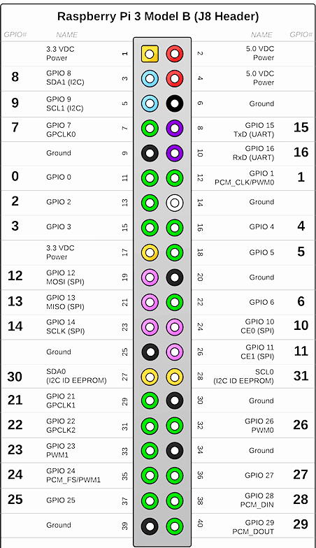
If you try to locate the SPI pins in the pin diagram above, you can see that GPIO10 and GPIO11 represent CE0 and CE1. A little closer inspection will also reveal the MISO, MOSI, and SCLK pins. Look out for them.
SPI In Action
Let’s build a real working circuit to demonstrate SPI in action. We will use the Raspberry Pi 3 as the SPI Master. To witness the capability of SPI for controlling more than one slave device, I have chosen two Arduino UNO boards as SPI slaves for this demo.

Arduino/Genuino Uno is a microcontroller board based on the ATmega328P (datasheet). Check out the documentation of Arduino UNO to understand its pin configuration. For this demo, I have set up each Arduino UNO (SPI slave) with two LEDs. At any given point of time, one slave will receive a command from the Raspberry Pi (SPI Master) to toggle the LEDs. The slave selection and command transmission are controlled by two push buttons.
Hardware Requirements
You will need the following hardware to execute this project.
- Raspberry Pi 3 Board*
- Arduino UNO* (2 nos.)
- Push Buttons (2 nos.)
- Resistors, 220 Ohms ( 6 nos.), 1k Ohms (2 no.), 2.2k Ohms ( 2 no.)
- 5mm LED (4 nos.)
- Breadboard (1 no.)
- Connecting wires
You can also get the electronic kit* that contains all the passive components such as resistors, buttons, connecting wires and breadboard.
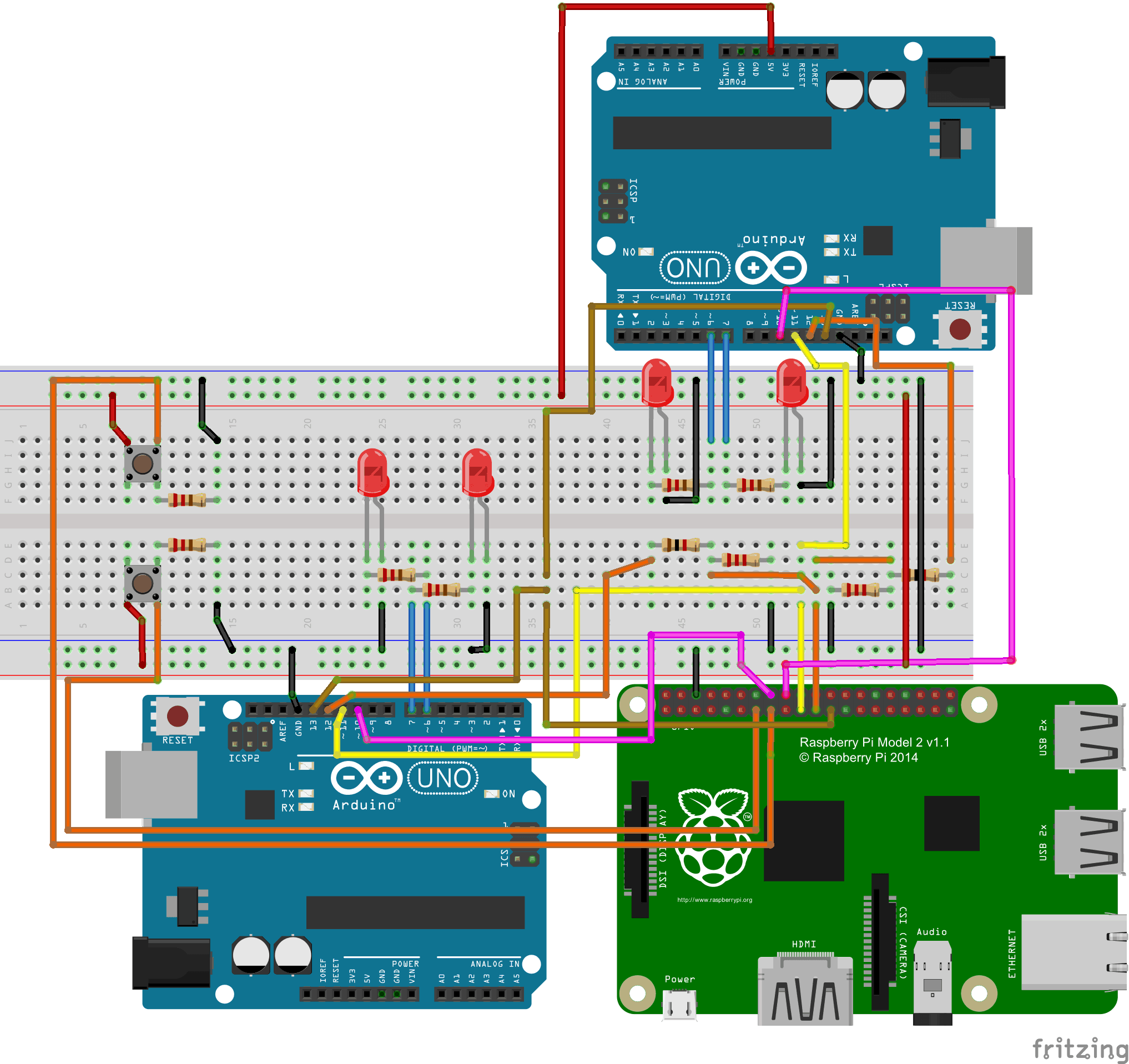
Here is the schematic connection for the hardware setup. Check out the resistor color codes to make sure you are using the correct pull up/down resistor configuration. The Vcc and ground connections are indicated with red and black wires respectively.
SPI Software Configuration
Once set up the circuit will function as follows.
(Note: At the time of writing this post, I did not have access to two Arduino UNO boards, hence I have used one UNO and one ATmega328P chip. Procedures given in the blog post are for Arduino UNO but will work with standalone ATmega328P also as long as you know how to program it.)
Sounds interesting? Let’s set up the software components for Arduino UNO and Raspberry Pi 3 to breath some life in this circuit.
Power on the hardware setup and make sure that you can access the Arduino UNOs via the USB of your computer and can login to Raspberry Pi terminal (via ssh or direct display connection). We are assuming that your Raspberry Pi has the Python interpreter installed along with the GPIO and spidev python libraries. If you are using Raspbian OS then these libraries should already present in your python environment.
Software setup for Arduino UNO
Before proceeding, we need to install Arduino IDE on a computer from which you will connect to the Arduino UNO.
Installing the Arduino IDE
– Download and Install Latest Version of Arduino IDE
– Start Arduino IDE and Plug one of the Arduino UNO board.
Step 1: Clone the GitHub repository under your home directory, using the following link
git clone https://github.com/suryasundarraj/rpi-series.git
Step 2: Open the file rpi-series/spi_communication/arduino_spi/arduino_spi.ino from this repo in Arduino IDE
Step 3: Select the Board from Tools – > Board – > Arduino UNO
Step 4: Select the USB Port from Tools – > Port – > COMXX
Step 5: Upload the Code on the Arduino UNO.
Repeat the step 5 for the second board as well. With this, both the boards are configured as SPI slave.
Software setup For Raspberry Pi
Before proceeding, make sure that you can access the Raspberry Pi 3 terminal, either directly or through SSH.
Step 1: Log into the raspberry pi console and clone the GitHub repository under your home directory, using the following link
git clone https://github.com/suryasundarraj/rpi-series.git
Step 2: Under the “rpi-series” navigate to “spi_communication“. Open the spi_communication folder using following command
cd rpi-series
cd spi_communication
Step 3: Run the script
python spiCommunication.py
Now the Raspberry Pi is configured as SPI master. Go ahead and play with the circuit and see if you can affect the toggling of LEDs connected to the two Arduino UNOs by selecting them through the push button.
Give it a try
Like I have said before, I would encourage you to try your hands on this circuit. SPI has got a lot fo real world applications and is ideally suited for one-to-many form of communication between hardware devices. So knowing it will be a great skillset for a hardware developer.
I will be back soon with one more hardware interface that is integral to the Raspberry Pi’s arsenal, the I2C. Until then, keep DIYing and don’t forget to comment in case you need my help.
Disclosure: * Denotes an affiliate link – if you click and make a purchase we may receive a small commission.

Hey there, Nice Tutorial! Just wanted to know if there is any pythonic method available on RPi to do this. As your code isn’t actually python. Help is appreciated! Thank you
Thanks, Vivek
Unfortunately, I also do not know about a pure pythonic way. I guess for accessing hardware stuff it is not possible to do it entirely on Python.