

Efficient and durable power supply is the backbone of any IoT Product. For a wearable or self-powered wireless device, power consumption and battery life are a big concern. In the coming years, with billions of “things” about to be connected to the Internet, power conservation is going to be a critical factor in deciding the economic feasibility of any IoT deployment. Apart from battery-powered devices, this is equally applicable for IoT gateways which run on 24/7 mains supply. In this post, we will discuss the essential design features needed to meet the requirements of an efficient power supply. Based on my experience of developing a power supply unit for a portable BLE IoT endpoint, I have also presented a prototype reference design of a battery charging circuit for standalone IoT devices.
Where Do We Start ?
So you are a hardware engineer, and you want to design a power source for an IoT device. At first, you might be tempted to choose a long lasting battery. But that’s not all. While choosing a battery, we must also take into account the following essential considerations
- mAh Rating of the Battery: The total amount of electric charge in mAh (milliampere hours) required by the device to last one charge. As a hardware engineer, you should estimate this by calculating the current consumption of the device within a time interval.
- Form factor: This refers to the physical size and shape of the device.As an example, for a wearable product, the form factor plays a significant role
- Usage Type: Single use ( throw away) or rechargeable battery
- Energy Density: The amount of electric charge stored in the region of space per unit volume or mass.
- Battery Lifecycle (for rechargeable batteries): Number of times a rechareable battery can be used after recharge . One complete discharge and charge operation of a battery consumes one life cycle. As an example, the Lithium Ion battery has a capability of 500 to 1000 recharge cycles.
Current State of Battery Technology
There are a wide variety of batteries available in the market, ranging in different form factors and electric charge capabilities. Here are some of the options available to us.
- Lithium Manganese Dioxide (Li/MnO2) – Single use
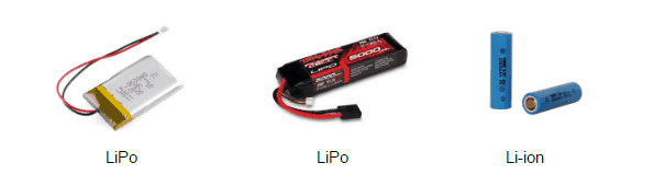
- Lithium Ion (Li-ion) – Rechargeable
- Lithium-Ion Polymer (Li-Po) – Rechargeable & Compact
- Nickel Cadmium (Ni-Cd) – Rechargeable, mostly used for laptops
- Nickel Metal Hydride (Ni-MH) – Rechargeable with higher capacity, mostly used for laptops
If the product is a “use and throw” kind, then Li/MnO2 battery is your best choice. It is available as a compact cylindrical or button-shaped package. If the product requires long lasting power and rechargeable option, then Lithium-Ion and Lithium Ion Polymer batteries are better choices.
Li-Ion & LiPo batteries offer thin packaging, which makes them very popular with mobile phones
Selecting a Battery for Power Supply
Selecting a battery in today’s electronic market is quite challenging. As a hardware designer, you have many options. But the first thing that you need to know is the mAh rating of your desired battery. This is directly proportional to power consumption. The more power the device consumes, the higher becomes the mAh rating that you need to look for. Apart from power consumption, you should have some idea about the form factor of the final product. If the product requires compact batteries, the best choice will be LiPo which is available in in various ultra-thin form factors.
General Techniques for Power Conservation
Here is a general strategy for power conservation. Most of the time, devices consume maximum power while communicating with interface peripherals or remote devices via wireless. Often, this happens as part of background activity. You would have surely experienced it when your mobile phone drains out faster with mobile data setting enabled. So as a thumb rule, put the device in sleep mode and wake up only when communication with the peripheral is needed. Most SoC vendors provide low power features for reduced power consumption and idle/hibernation modes. These features allow the device to be programmed to bring down the hardware to sleep state. Apart from this, the device should regularly monitor the battery level. When the battery is about to drain completely, the power supply hardware should power off or pull the device into hibernate state to avoid further damaging the battery.
For some more in-depth coverage on efficient power conservation strategies, you can read this article at engineering.com.
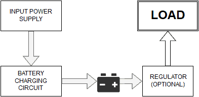
Building a Battery Charging Circuit for an IoT Device
In the case of IoT, most devices need rechargeable batteries. The obvious choice is LiPo or Li-Ion battery. Now let’s design a battery charging circuit. But before we get into the nitty-gritty of design, let us look at some of the essential features that every battery charging cum power supply circuit must have.
- Deep drain protection: This is also known as under voltage cut-off. When battery charge level goes below the working voltage, the power supply circuit must break down the connection between the battery and device to save the battery from damage.
- Over Current Protection: The charging circuit provides overcurrent protection when the input current goes beyond 1A. The charging current is programmed using an external resistor.
- Over-voltage charging protection: During charging, when the battery transitions from “constant-current” to “constant-voltage” state, the charging circuit must halt. This is to prevent battery damage from over-voltage charging.
- Charging Status Indication: Charging circuit must provide a visual indication of the charging status. LED can be used as status indicator for charging / full charge status monitoring.
Note: Rechargeable Lithium battery charger works on the principle of high-performance linear charge with 1% power dissipation with charge accuracy of 1.5%. The charger circuit has an over-current protection of up to 3 Amps.
Battery Charger Schematic
As a thumb rule, for charging a 3.7v LiPo / 3.6v Li-ion battery, the charger circuit should drive 4.5 V to 5.5 V and 1A current.
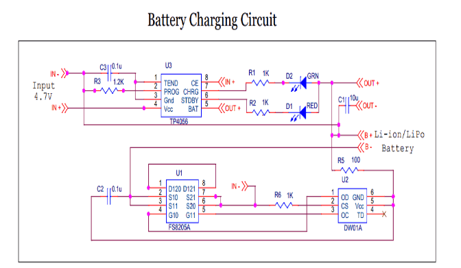
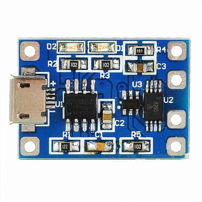
The circuit contains three major components,
- TP4056 Charger IC
- 8205A MOSFET
- DW01A Battery Protection IC
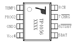
TP4056 Charger IC
The TP4056 is a complete constant-current/constant-voltage linear charger for single cell Lithium-Ion batteries. It has thermal feedback mechanism to regulate the charge current to limit the die temperature during high power operation or high ambient temperature. The charge voltage is fixed at 4.2V, and the charge current can be programmed externally with a single resistor. The TP4056 automatically terminates the charge cycle when the charge current drops to 1/10th the programmed value once the battery attains maximum voltage.
Polymer Battery Protection IC : DW01A
The DW01-A battery protection IC with MOSFET 8205A is designed to protect Lithium-Ion/Polymer batteries from damage due to overcharge, over discharge, and/or overcurrent. This also protects against degradation of recharge lifecycle. The ultra-small package along with minimum external components makes it ideal for integrating the DW01-A into the limited space available within a battery pack. It provides an accuracy of ±50mV overcharging detection voltage which ensures safe and full utilization of charging. It also has a very low standby current which drains very little charge from the battery while in storage. The MOSFET 8205A makes it possible for users to monitor the status of the Lithium-Ion rechargeable battery. A built-in voltage detection circuit with high accuracy and a delay circuit aids in monitoring the battery.
Commercial Availability
The above circuit schematic is also available as off the shelf PCB unit, and most local electronics market dealers would stock it. Check the specification of the circuit you are buying to see if the components used are the same as described in the schematic here.
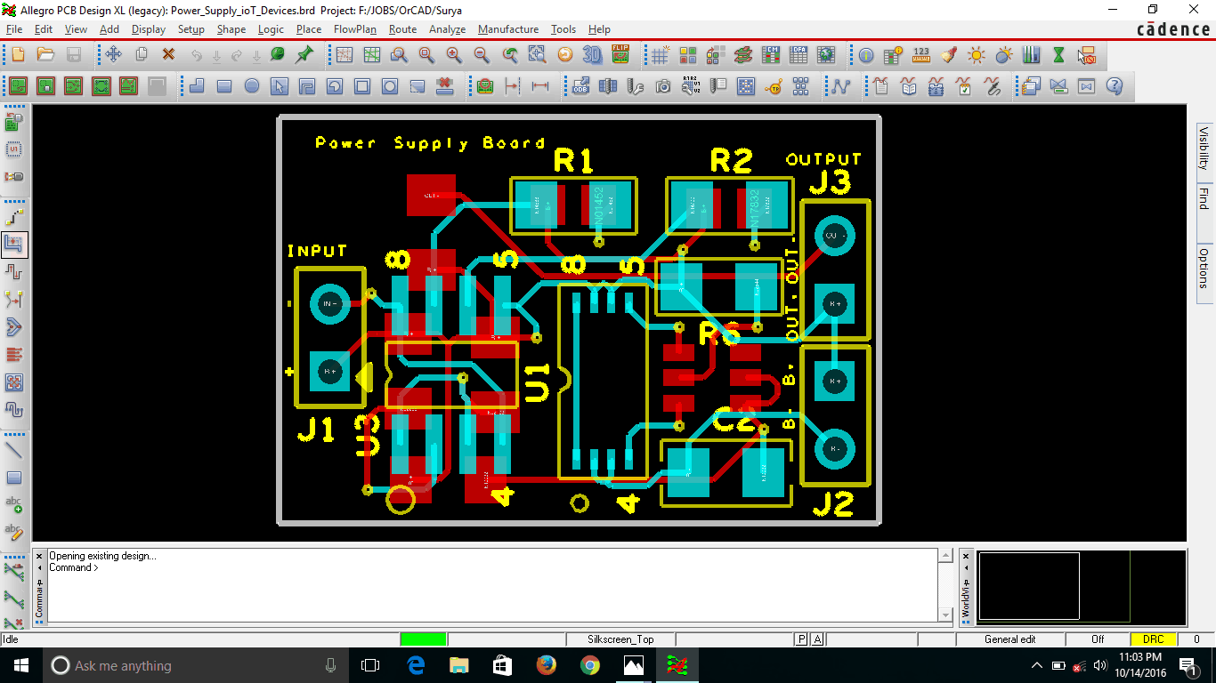
For the benefit of those curious minds, I am offering a bonus. If you would want to design your PCB and perhaps do some modifications or enhancements to the existing circuit, I have provided the Allegro OrCAD PCB design software files.
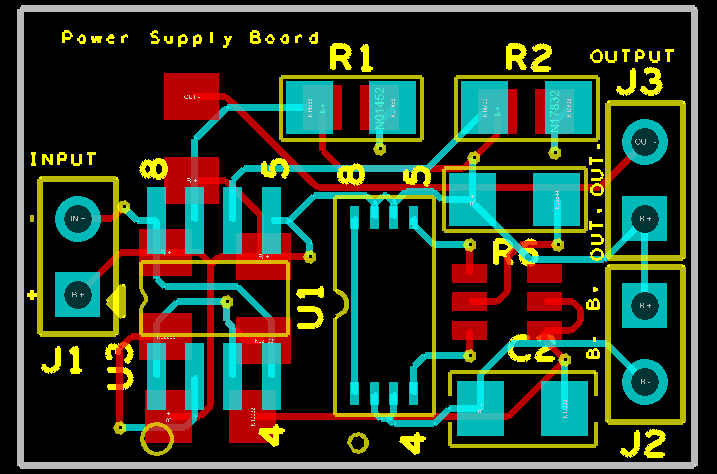
The entire OrCAD project folder is available in GitHub under this repository.
Power Up
Thumbs up! We have designed a high-performance power supply with battery charging circuit for powering your IoT product. There is only one limitation. This circuit does not provide safety on reverse polarity which can damage the batteries. So make sure that the battery is hooked up to the charger with the right polarity.
If you are working on designing power supply systems for IoT then I would love to hear from you. Please share your experiences or any specific challenges that you might have overcome through your design. And in case you want to replicate this design in your work and have any technical doubts then you can post your comments below and I will get back to you.

Hi,
Good write up!
My doubts,
How long the battery could be on charge?
The state of on- charge time period?
If I connect devices with Bluetooth or pair with external devices , how far the drain protection holds good?
Thanks Sairam,So on your doubts
1)The charging circuit is designed in such a way that the circuit will cut-off when it reaches out the transition from constant current to constant voltage,and charging current drops.
2)The time period for charging varies with battery total mAh and maximum charging current. Generally with 5V 1A charger for 1000mAh battery, It takes 50mins On-Charge time period.
3) Drain Protection cut-off the battery, only when the voltage goes below 2.2 V